When I just started programming, my first instinct when developing software was to dive straight into writing code:

Sure, you will make significant progress initially. However, over the years, I’ve realised that this is probably not the best idea. Without forward planning, I often need to backtrack, or miss out some requirement, or accidentally introduce bugs. Software development is a messy process as it involves the creation of something new. To lend some structure to software development, let us take a look at the Software Development Life Cycle (as explained in an EdX course created by UT Austin professors Jonathan Valvano and Ramesh Yerraballi).
Software Development Life Cycle
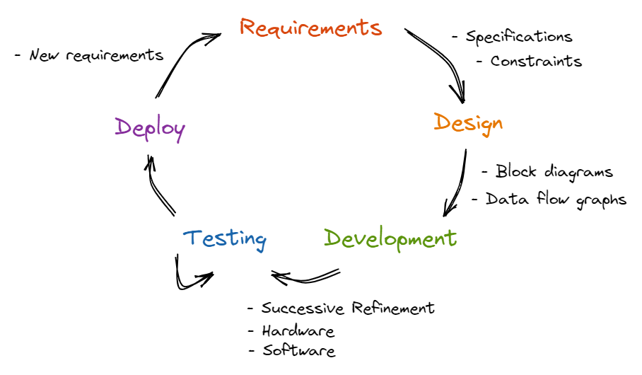
The Software Development Life Cycle (SDLC) describes and codifies the main steps we take in developing software. For large, complex projects, we will traverse through the SDLC multiple times. For simple projects, a single pass might suffice. We will explore each step next.
Step 1: Requirements
We first need to collect the requirements of our project. In a school setting, this might already be given to you as part of your coding assignment. Else, you should clarify with your instructor about the requirements. In a corporate setting, you will talk to current or potential clients and users to gather the requirements.
The purpose of collecting the requirements is threefold:
- This better defines the problem you are solving by explicitly stating what your system should do. This will guide your design and development in the right direction, ensuring that what you build will fulfill the needs of your clients and users.
- This gives context to what you are working on. Understanding the circumstances that form the setting for the problem you are solving will influence how you design and implement your system. For example, knowing that your software will be running in a real-time embedded system with limited memory and processing power will inform you that you should implement your system in C rather than Python.
- This prevents scope creep. As you build your system, it’s common for you or your clients to want additional features. However, this not only increases the amount of development work (which might cause the project to overrun the deadline), but also might result in conflicting requirements. Explicitly defining the requirements will make it easier to manage development work and additional features.
A Requirements Document is a template that you can use to explicitly define the requirements of your project. It should state what the system should do, not how the system will do it. IEEE publishes a number of templates such as IEEE STD 830-1998. Here is the one taken from the EdX course Embedded Systems - Shape The World: Microcontroller Input/Output:
- Overview
- Objectives: Why are we doing this project? What is the purpose?
- Process: How will the project be developed?
- Roles and Responsibilities: Who will do what? Who are the clients?
- Interactions with Existing Systems: How will it fit in?
- Terminology: Define terms used in the document.
- Security: How will intellectual property be managed?
- Function Description
- Functionality: What will the system do precisely?
- Scope: List the phases and what will be delivered in each phase.
- Prototypes: How will intermediate progress be demonstrated?
- Performance: Define the measures and describe how they will be determined.
- Usability: Describe the interfaces. Be quantitative if possible.
- Safety: Explain any safety requirements and how they will be measured.
- Deliverables
- Reports: How will the system be described?
- Audits: How will the clients evaluate progress?
- Outcomes: What are the deliverables? How do we know when it is done?
After filling in the Requirements Document, we will turn the requirements into specifications and constraints. Specifications are detailed parameters for how the system should work. For example, a requirement might state that the system should be a handheld device, while a specification would give the exact size of the device. A constraint is a limitation within which the system must operate.
Step 2: Design
After formalizing the requirements into a Requirements Document and generating the specifications and constraints, we can turn to designing the system. Here, we build a conceptual model of the hardware/software system. We can make use of data flow graphs and call graphs to build this conceptual model.
Data Flow Graph
A data flow graph is a block diagram of the system showing the flow of information.
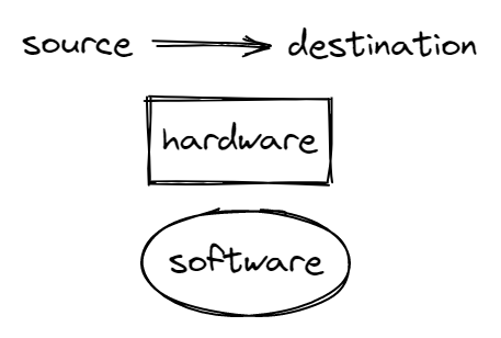
Arrows point from source to destination, the rectangles represent hardware components and ovals represent software modules.
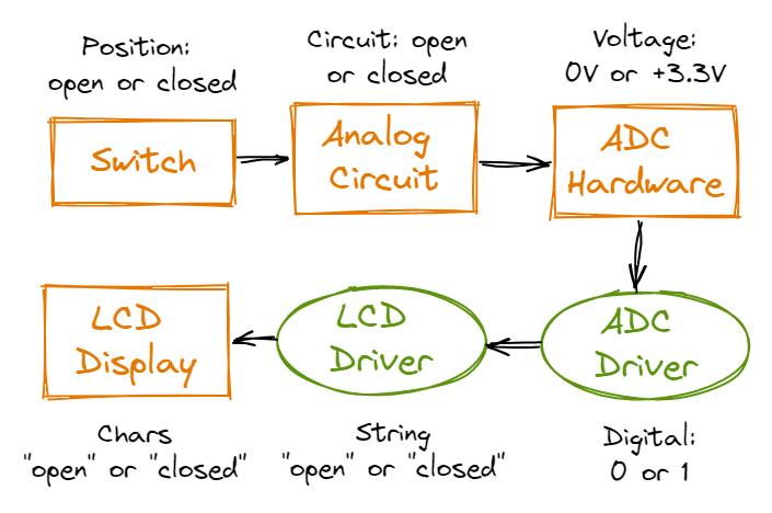
In the data flow graph above, information flows from the switch hardware component to the analog circuit to the Analog to Digital Converter (ADC) which translates information from voltages to digital 0s and 1s, which is then converted to “open” and “closed” strings and ultimately displayed by the LCD display hardware component.
A data flow graph is useful as it allows you to understand what modules should make up your system and what each module should do. At the core of any system is the manipulation and transformation of data. By building a data flow graph, you know the inputs and outputs to your system, as well as how data changes between modules and hence roughly what each module should do.
Call Graph
A call graph is a graphical way to define how the software/hardware modules interconnect. An arrow points from the calling routine to the module it calls. Again, rectangles represent hardware components while ovals represent software modules.
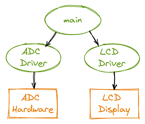
This is a high-level call graph that only shows the high-level hardware and software modules. A detailed call graph would include each software function and I/O port.
A call graph is useful as it defines the hierarchy of software and hardware modules. As an arrow points from the calling module to the module it calls, the calling module is at a higher level of the hierarchy and “controls” the module being called. For example, the ADC driver module controls and is responsible for calling the ADC hardware module.
This hierarchy is also a useful visualisation of the level of abstraction of each module. This aids in the writing of clean code. As the main module calls the ADC driver module, the main module is at a higher level of abstraction than the ADC driver module. Hence, in writing the main module, we do not need to be concerned about the details of how the ADC driver module controls the ADC hardware module.
Step 3: Development
How then should we turn our conceptual model and requirements into a software algorithm? We use the process of Successive Refinement. This means that we start with a task and keep decomposing it into a set of simpler sub-tasks until it is so simple it can be converted into software code. A task can be decomposed in four ways:
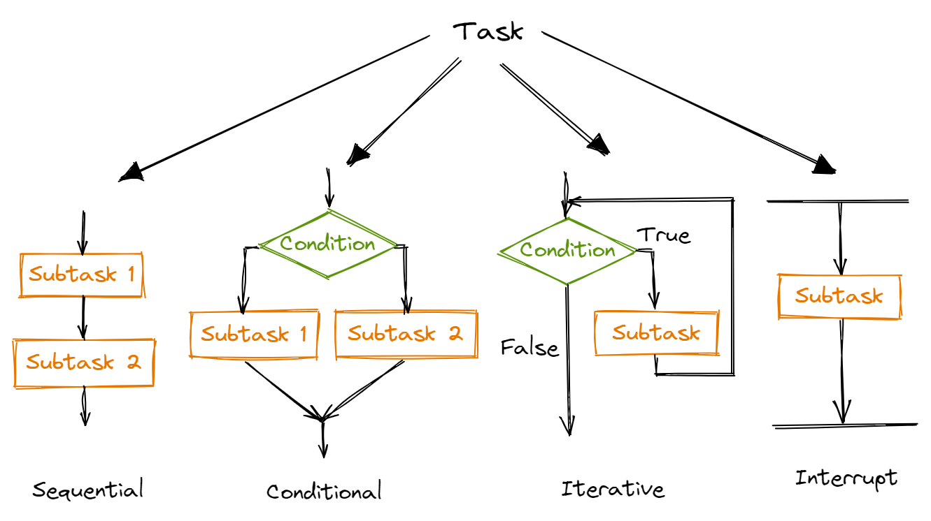
We keep decomposing a task into one of these 4 sub-tasks until we have a set of sub-tasks that are sufficiently detailed to write it as code. Successive refinement is a useful technique as it guides you to plan your system at the right level of detail at each step. For example, let’s say you need to write a program to calculate the mean score in the most recent Physics exam. On the first step of Successive Refinement, you would plan your program as such:
- Open the excel file containing the exam scores of all students
- Calculate the mean exam score
- Write the mean exam score to a new file
At this step, you would not want to get into the weeds of how to open the file and how to loop through all the cells in the excel file as that would be too much details.
Successive Refinement often feels so natural as it is a form of hierarchical planning, which humans constantly use when accomplishing tasks. For example, when thinking about how to bake a cake, we would first plan at a high level: make cake batter, bake cake layers, make frosting, layer cake and frosting, decorate cake. We would then delve into the details for each high-level step.
Another reason why Successive Refinement is so useful is that it explicitly documents the design decisions made when decomposing a task into sub-tasks. This allows us to consider the pros and cons of the chosen solution and of alternative solutions.
Here’s a great read: Program Development by Stepwise Refinement by Niklaus Wirth that explores the idea of Successive/Stepwise Refinement in greater detail.
If our task involves the use of hardware, we can first simulate running the software to ensure that the software runs as intended. Then, we can task the software directly on our hardware.
Step 4: Testing
During the testing phase, we evaluate the performance of our system. First, we write unit tests to test the correctness of each function. After validating the functions, we write integration tests to test the interactions between different functions. Lastly, we use careful measurements to optimise performance such as static efficiency (memory requirements), dynamic efficiency (execution speed), accuracy and stability. Other considerations include the ease of software maintenance.
Unit Testing
Unit tests test the correctness of your functions in isolation. There are two kinds of unit tests: state-based and interaction-based. State-based unit tests verifies whether your function produces the correct result or state. Interaction-based unit tests verifies whether your function properly invokes certain functions. To comprehensively test a function, your suite of unit tests should feed every possible type of input to the function and observe whether it behaves correctly. For example, consider a function that calculates the sum of two inputs. Our unit tests should input positive numbers, zeros, negative numbers, strings, lists, etc.
As unit tests should test a function in isolation, other parts of the system should be mocked. For example, if your function accesses a database, your unit test should create a mock database with known and fixed data so that the function can be tested independent of the state of the database.
Testing in isolation is useful as it naturally isolates the source of bugs. If a bug is discovered when testing the whole system, it isn’t clear which part of the system causes the bug. Testing in isolation is also useful in revealing the dependencies between a function and other parts of the system. This allows us to re-consider our design decisions in order to remove some of these dependencies.
Integration Testing
Integration tests test how different parts of your system work together in a close-to-real-life environment. They validate complex and higher-level scenarios. There are a few common approaches to integration testing: big-bang, top-down and bottom-up testing.
The big-bang approach integrates all modules at once and tests them as a unit. Top-down testing is an incremental approach that tests the highest-level module first and gradually proceeds to the lower modules. Bottom-up testing, as its name suggests, is the opposite of top-down testing and involes testing the lower-level modules first and gradually proceeding to the higher-level modules.
Step 5: Deployment
Lastly, after successfully testing our system, we can deploy it for use. Based on client usage, there might be additional requirements and constraints. Clients might also discover some bugs in our system. We then loop through the SDLC as needed.
Closing Thoughts
The Software Development Life Cycle is one of many ways to structure the creative and messy process of software development. Given the almost limitless number of ways to develop a project, the SDLC systematically guides us through this process and compels us to consider each design decision. It is also useful because it explicitly documents the various steps of software development. It is especially useful when working on large projects and when working in a team of developers.