It’s been more than a year since I last wrote my first blog post last summer. Whoops.
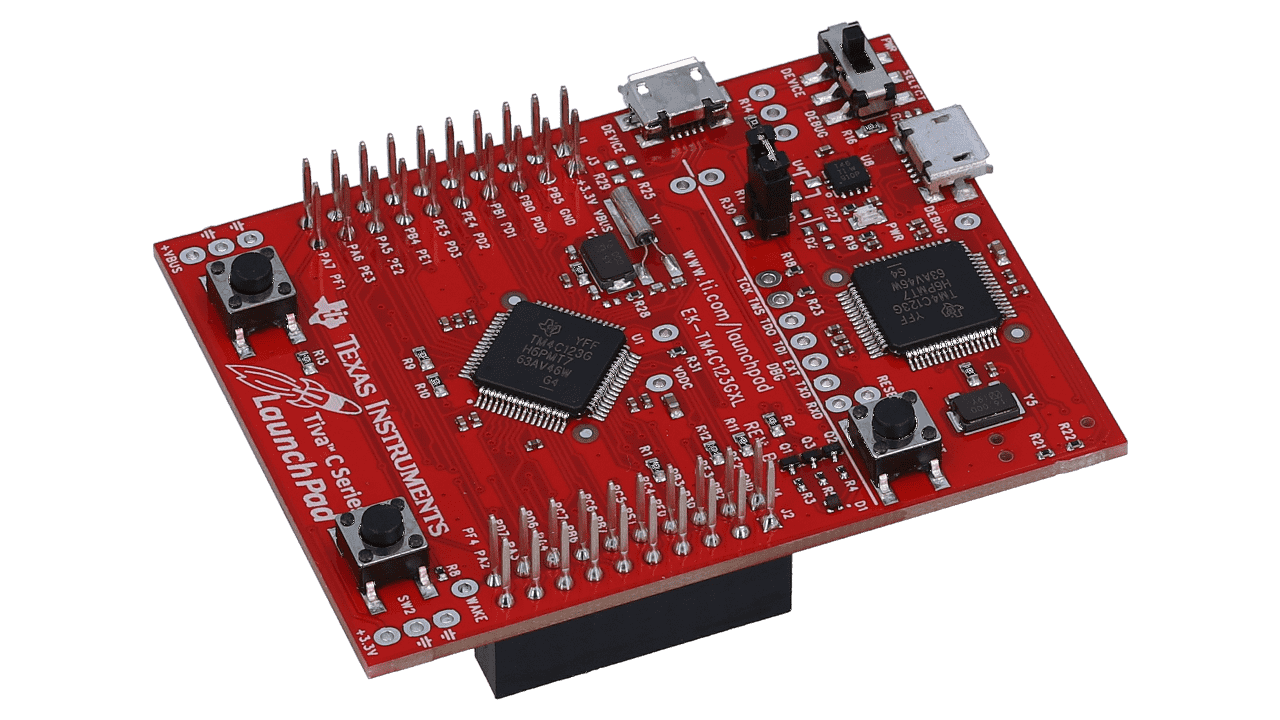
Since then, I’ve travelled a lot during my senior year and recently graduated from Brown University! Though I enjoyed my time at Brown immensely, one thing I regretted not doing at Brown was taking a class in embedded systems. As such, I thought it would be fun to delve into the fascinating world of embedded systems, microcontrollers and circuits. To kickstart my journey, I signed up for a (free!) course on EdX created by UT Austin professors Jonathan Valvano and Ramesh Yerraballi. The microcontroller used in this course is Texas Instruments’ EK-TM4C123GXL:
1 Embedded Systems?
First, what is an embedded system? As a system, an embedded system is a combination of a computer processor and computer memory with the means to exchange data with the external world using input/output (I/O) devices. A microcontroller like the EK-TM4C123GXL is a small computer that contains a processor, memory and I/O. Being embedded, an embedded system is often a part of a complete device that has electrical and mechanical parts.
Embedded systems are ubiquitous and wide-ranging in size, complexity and cost. They can be found in homes, such as refrigerators and microwave ovens, as well as in missile defense systems and aircrafts.
2 Some Basics
Despite being so varied, embedded systems stem from the same foundations. Let us briefly explore these.
2.1 Circuitry
Hardware components in embedded systems are usually controlled using electronic circuits. An electronic circuit is composed of individual electronic components, such as batteries, resistors and LEDs, connected by conductive wires.
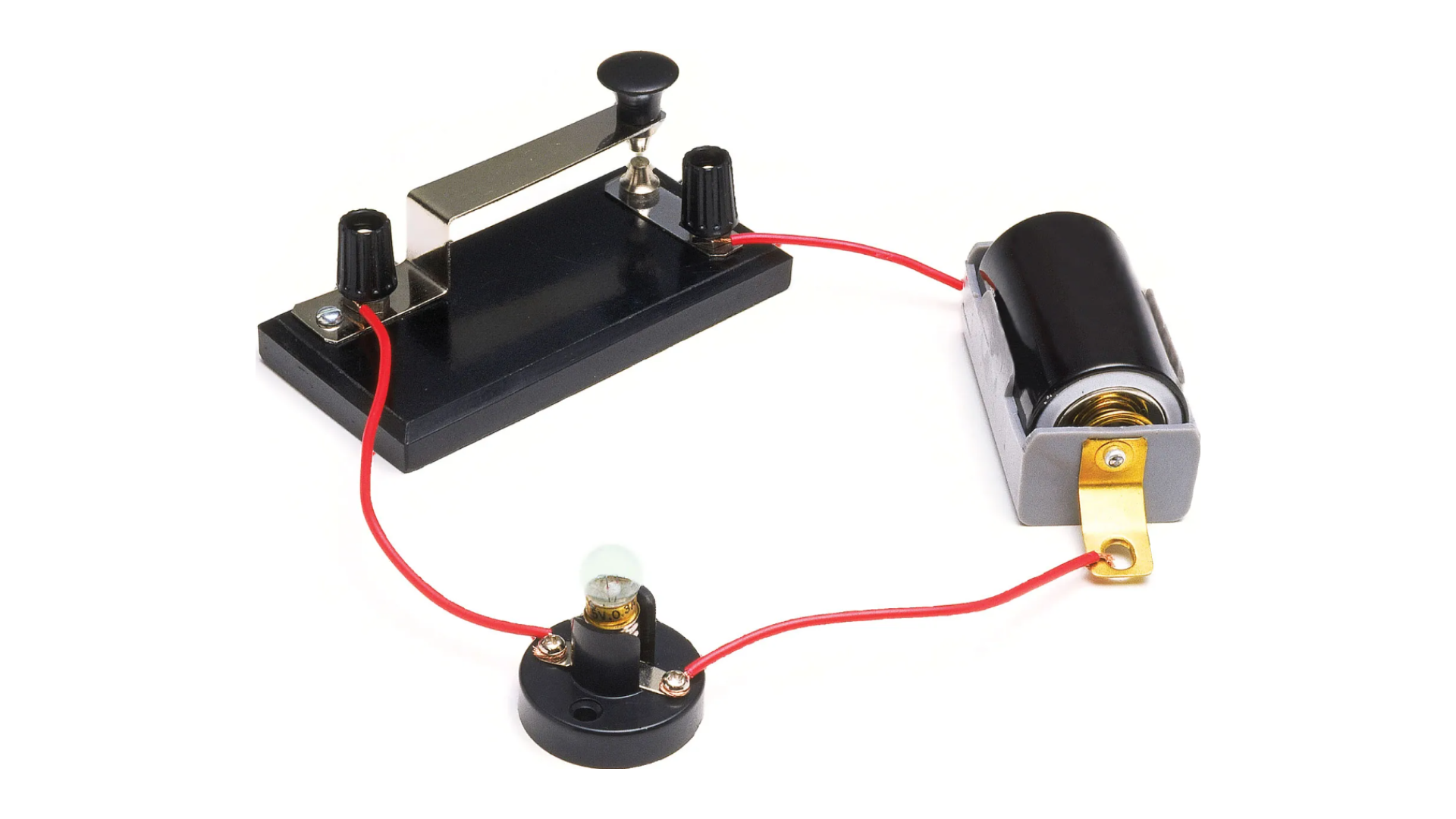
Current, \(I\), is defined as the movement of electrons. 1 ampere (A) of current is \(6.241 \times 10^{18}\) electrons per second.
Voltage, \(V\), represents the potential difference between two points. It is the electromotive force or potential to produce a current. Voltage is measured in volts (V).
Resistance, \(R\), is a force that counteracts the flow of electricity. Resistance is measured in ohms (\(\Omega\)).
Ohm’s Law defines the relationship between current, voltage and resistance: (expand more on how this is used)
\[V = IR\]In any electronic circuit, it is important to figure out what is the current flowing through a component, the potential difference between any two points in the circuit and the resistance of a component.
2.2 Digital Logic
The smallest unit of data a computer can process and store is a bit or binary digit. A bit can only be in one of two states and is often represented as 1 or 0. It can also be represented as on or off, true or false, yes or no. However, in order for the microcontroller to control electronic components in an electrical circuit, it must find some way to convert bits in the software into voltages. This is called Digital to Analog conversion. When the microcontroller outputs a “1”, the output voltage needs to be higher than some threshold. Conversely, when the microcontroller outputs a “0”, the output voltage needs to be lower than some threshold.
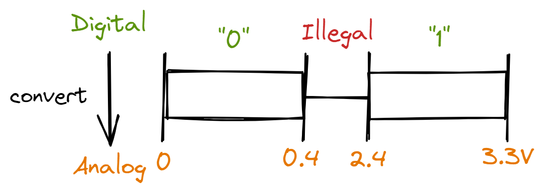
For the EK-TM4C123GXL, a digital “0” is converted to an output of 0-0.4V. A digital “1” is converted to an output of 2.4-3.3V. Anything between 0.4V and 2.4V is considered illegal.
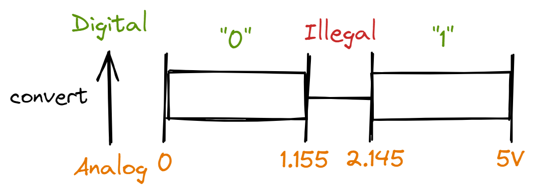
For the EK-TM4C123GXL, an input of 0-1.155V is converted to a digital “0”. An input of 2.145-5V is converted to a digital “1”. Anything between 1.155V and 2.145V is considered illegal. If the microcontroller outputs a sequence of bits, it will produce a waveform:

This conversion allows us to interface software (digital) with hardware (analog).
2.3 GPIO Pins
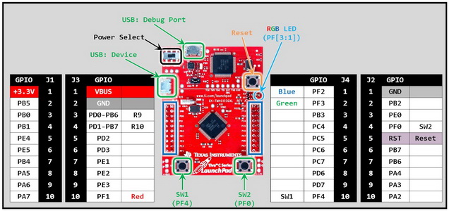
General-purpose input/output (GPIO) pins are generic pins on a microcontroller that can be controlled by the software program at runtime. For example, if the program wants to output a digital “1” at GPIO pin PE4, the PE4 pin will output 3.3V. GPIO pins are used to interface with electronic circuits and external devices.
The diagram below is from AirSupplyLab.
3 I/O Ports
Rather than directly controlling each individual GPIO pin, we group GPIO pins into various I/O PORTs. On the EK-TM4C123GXL, there are 6 PORTs ranging from PORT A to PORT F. In the previous diagram, we see that each GPIO pin is labelled in a particular manner: P + (PORT) + (Pin number). For example, PE4 is in PORT E and has pin number 4.
How do we actually read and write from these GPIO pins and PORTs? As the PORTs are mapped to particular memory addresses, we directly read from and write to these memory addresses.
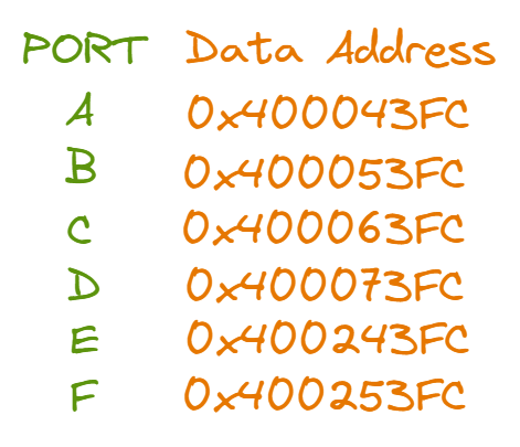
#define GPIO_PORTA_DATA_R (*((volatile unsigned long *) 0x400043FC))

unsigned long In; // input from PORT A
unsigned long Bit1; // input from PA1

void Read_PORTA(void){
    In = GPIO_PORTA_DATA_R;
}

void Write_PORTA(void){
    GPIO_PORTA_DATA_R = 0x26; // 0x26 is 00100110
    // This sets PA1, PA2 and PA5 to 1,
    // and clears PA0, PA3, PA4, PA6 and PA7 to 0
}

void Read_Bit1(void){
    Bit1 = GPIO_PORTA_DATA_R & 0x02; // mask for Bit 1
}

void Write_Bit1(void){
    GPIO_PORTA_DATA_R |= 0x02; // 0x02 is 00000010
    // This sets PA1 to 1
    // All the other pins are unaffected
}
In the Read_PORTA() function above, we read in the input from all PORT A pins PA0-PA7. On the other hand, in the Read_Bit1() function, we only read in the input from pin PA1. Similarly, Write_PORTA() writes to pins PA0-PA7 while Write_Bit1() only writes to pin PA1.
Now that we can read and write from the GPIO pins, we can embark on a lab project that ties all these concepts together!
4 Traffic Junction
At the crossroads of a road spanning East-West and a road spanning North-South, there is a traffic junction. There is a traffic light for each road and pedestrian lights for pedestrians.
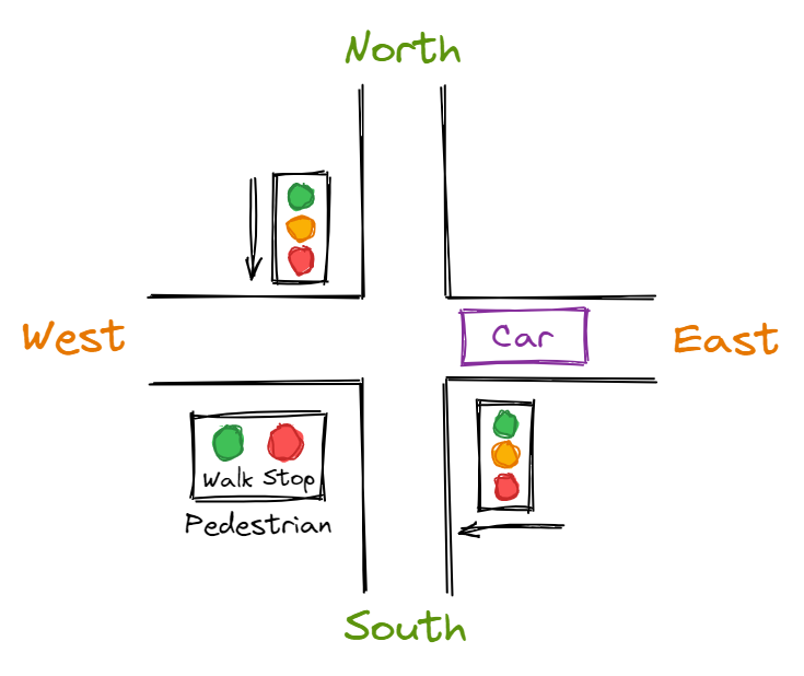
Here are the requirements for our traffic junction:
- Each traffic light must be one of red, yellow or green, and only one pedestrian light should be on.
- Only one road’s traffic light must be green or yellow at a time. The other road’s traffic light must be red.
- When the “Walk” light is on or the “Stop” light is flashing, both traffic lights must be red.
- When multiple sensors are true (eg. there are cars on both roads), cycle the traffic lights and pedestrian lights to service each group.
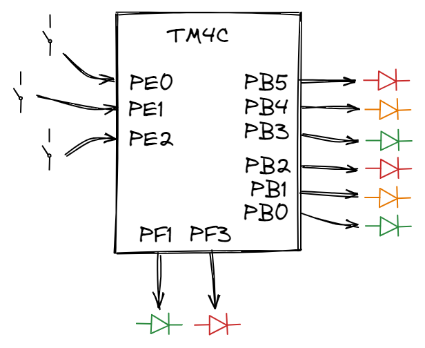
To start building the traffic junction, let us first consider what the inputs and outputs are for our system. There are 3 inputs:
- 1 car sensor for the East-West road - it will provide input to GPIO pin PE0
- 1 car sensor for the North-South road - input to PE1
- 1 pedestrian sensor - input to PE2
There are 8 outputs:
- 3 LEDs for East-West traffic light
- Red LED - receive output from PB5
- Yellow LED - receive output from PB4
- Green LED - receive output from PB3
- 3 LEDs for North-South traffic light
- Red LED - receive output from PB2
- Yellow LED - receive output from PB1
- Green LED - receive output from PB0
- 2 LEDs for the pedestrian lights
- Green LED - receive output from PF3
- Red LED - receive output from PF1
Here’s a data flow graph that visualises how information flows from the inputs to the EK-TM4C123GXL to the outputs:
To translate this data flow graph into an actual electrical circuit, let us first see how to connect a switch and an LED to the microcontroller.
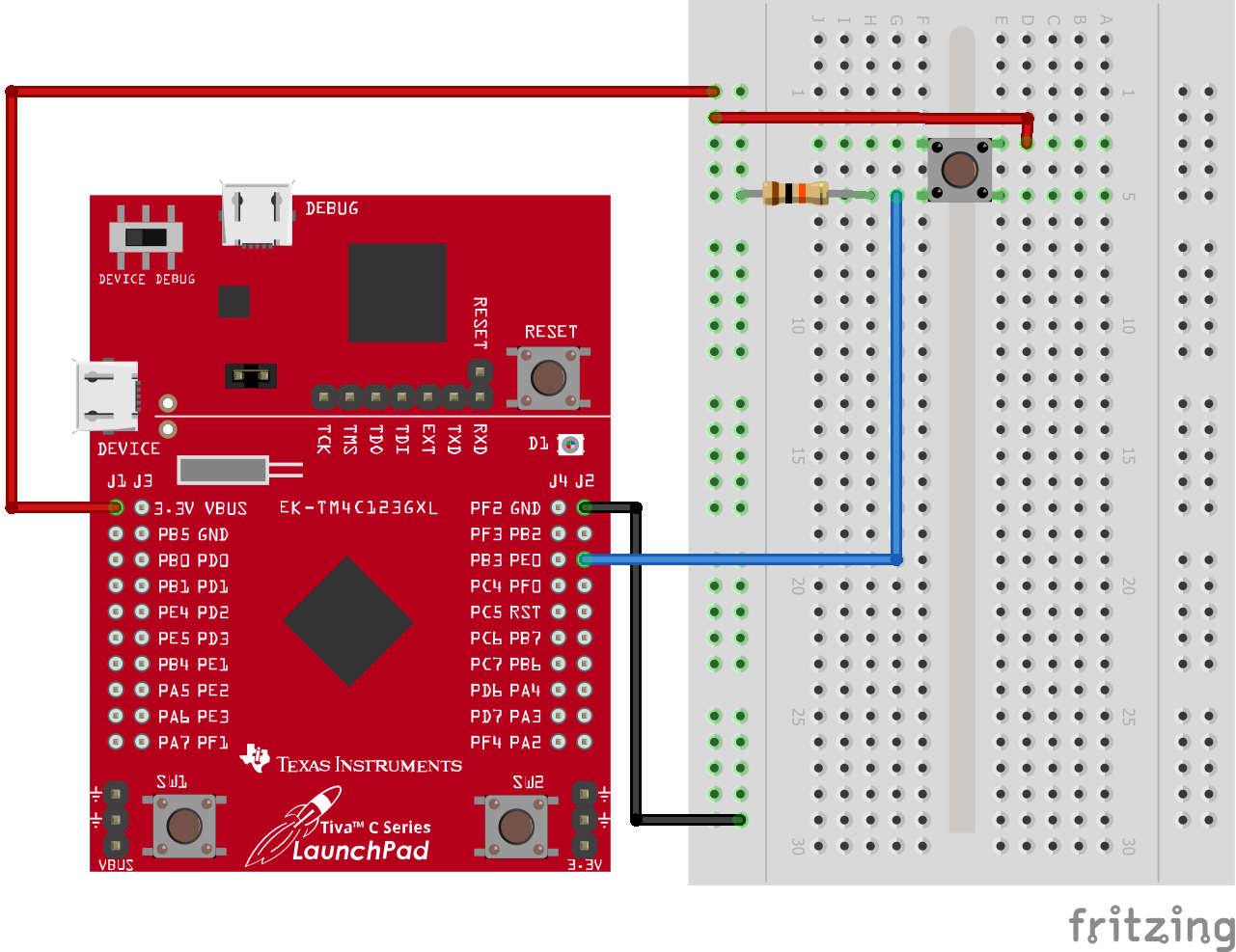
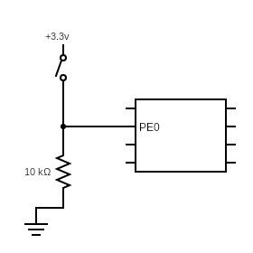
The breadboard and schematic diagrams above illustrate how to connect a switch to the microcontroller. When the switch is open, PE0 is connected to ground (GND) and so the input to PE0 is 0V (“0”). When the switch is closed, PE0 is connected to the +3.3V source and hence the input to PE0 is 3.3V (“1”). A 10k\(\Omega\) resistor is connected to GND so that most of the current will flow between the +3.3V source and PE0.
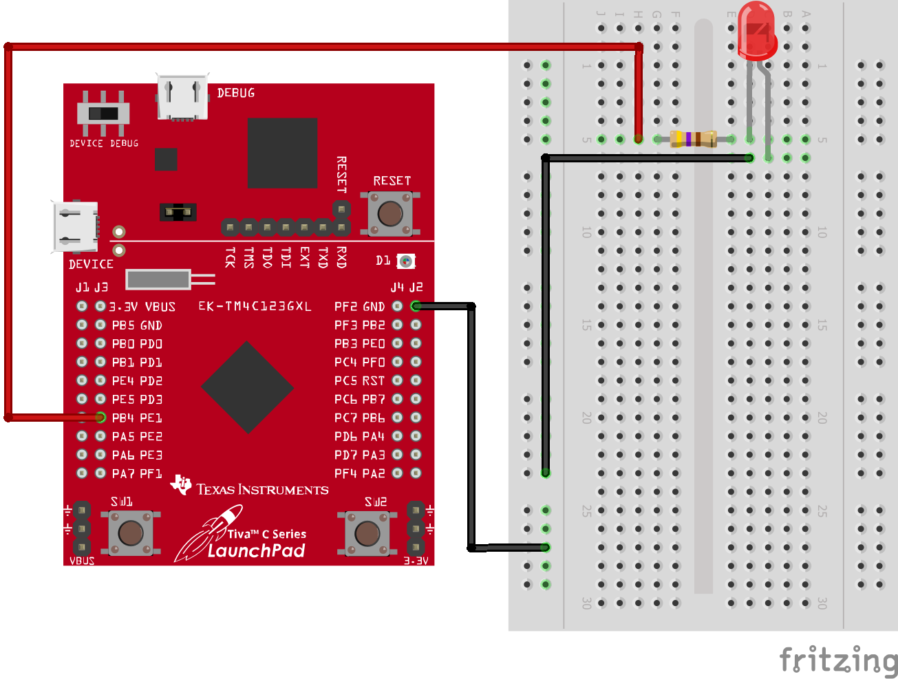
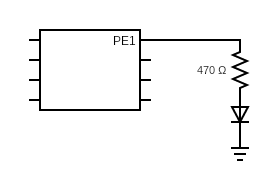
The breadboard and schematic diagrams above illustrate how to connect an LED to the microcontroller. When PE1 outputs 0V (“0”), no current flows through the LED. When PE1 outputs +3.3V (“1”), a current flows through the LED and the LED lights up. We put a 470\(\Omega\) resistor so that the current flowing through the LED is not too large.
Now that we know how to connect switches and LEDs to the microcontroller, let us translate the data flow graph into an actual electrical circuit.
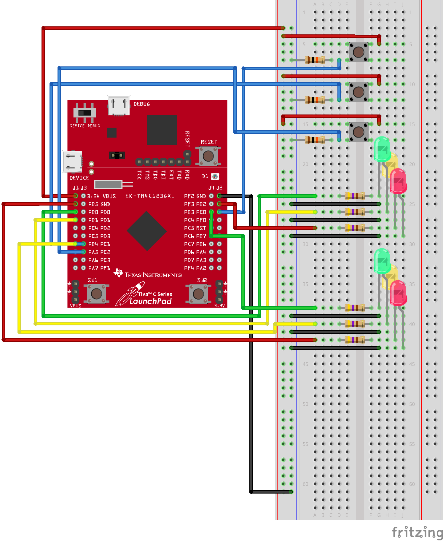
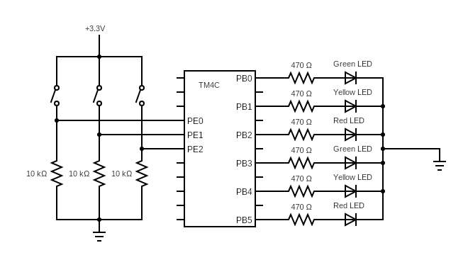
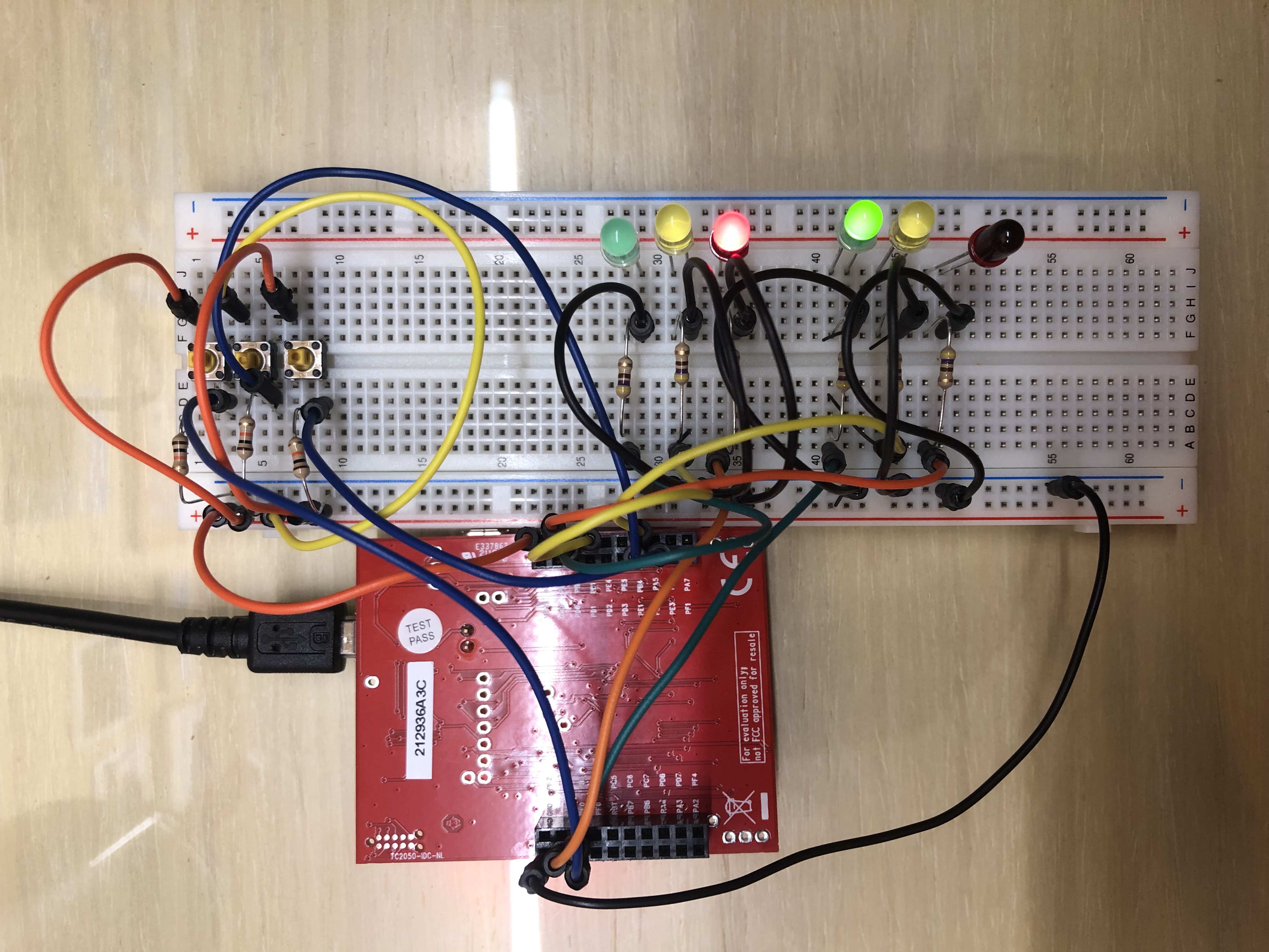
As seen in the diagrams above, there are 3 inputs and 8 outputs. The three switches represent the East-West car sensor, North-South sensor and pedestrian sensor. The 6 LEDs represent the traffic lights for both roads. You might be wondering, where are the LEDs for the pedestrian lights? PF1 and PF3 are connected to a RGB LED on the EK-TM4C123GXL board itself.
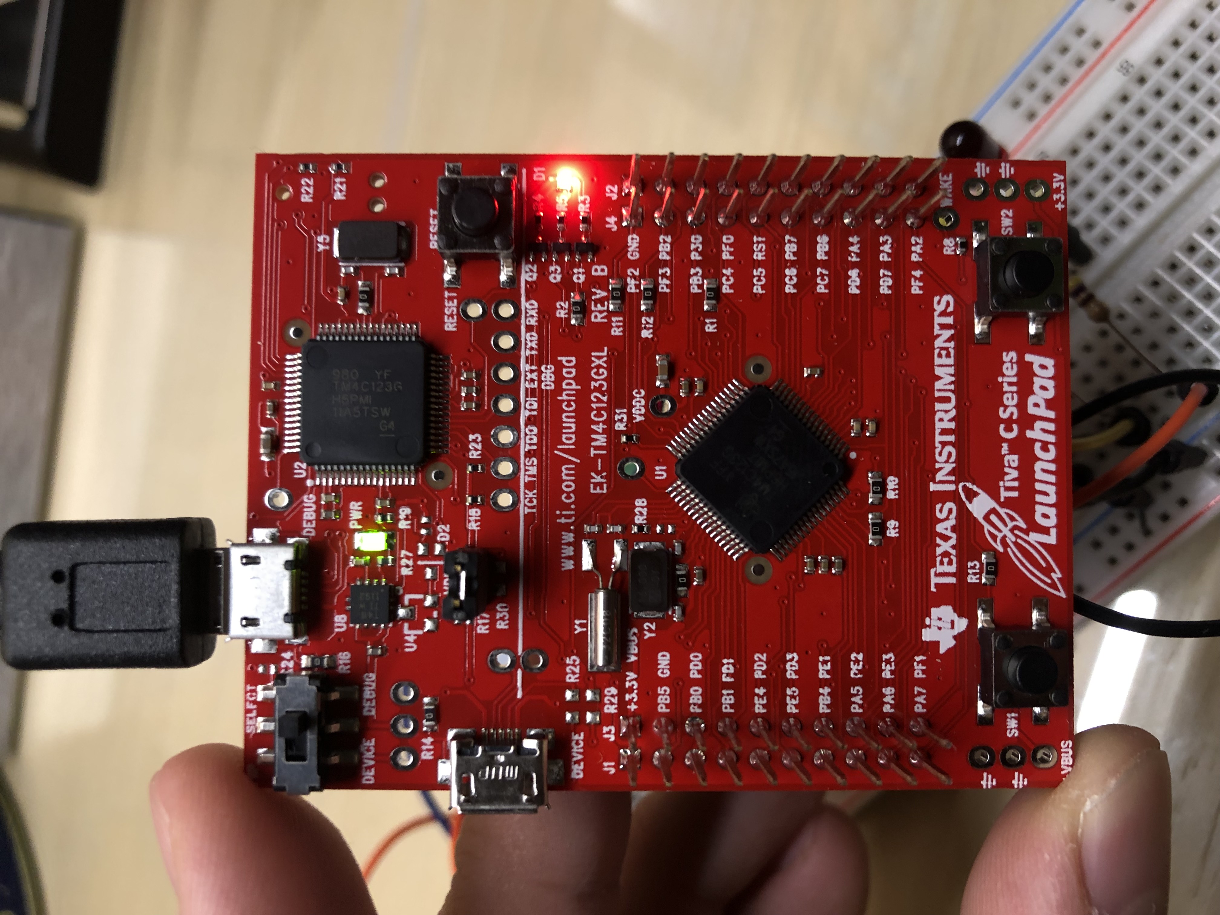
Now that we have the electrical circuit set-up, we can start coding the software program. In the code block below, there are functions for reading in inputs and writing out outputs. The full program is a fair bit complicated as it uses finite state machines so we won’t discuss that here.
#define GPIO_PORTB_DATA_R (*((volatile unsigned long *) 0x400053FC))
#define GPIO_PORTE_DATA_R (*((volatile unsigned long *) 0x400243FC))
#define GPIO_PORTF_DATA_R (*((volatile unsigned long *) 0x400253FC))

unsigned long Sensor; // input from PORT E

void Read_Sensor(void){
    Sensor = GPIO_PORTE_DATA_R;
}

void Write_TrafficLights(unsigned long output){
    GPIO_PORTB_DATA_R = output;
    // Eg. If output is 0x14 -> 00010100
    // This means that PB2 and PB4 are "1" while the rest are "0"
    // The East-West traffic light is Yellow
    // and the North-South traffic light is Red
}

void Write_PedLights(unsigned long output){
    GPIO_PORTF_DATA_R = output;
    // Eg. If output is 0x08 -> 00001000
    // This means that PF3 is "1" while PF1 is "0"
    // And that the pedestrian light is green
}
Here’s the final result!
In the video shown, the North-South traffic light and pedestrian light are initially red while the East-West traffic light is green. After pressing the second switch (North-South car sensor), the East-West traffic light turns from green to yellow to red while the North-South traffic light turns green. When the third switch (pedestrian sensor) is pressed, the North-South traffic light turns from green to yellow to red while the pedestrian light turns green. When the first switch (East-West car sensor) is pressed, the pedestrian light flashes red three times before staying red while the East-West traffic light turns green.
5 Closing Thoughts
I’ve always found embedded systems fascinating as they allow software programs to concretely affect the real world. Although the traffic junction project wasn’t too complicated, it effectively introduced the foundations of electrical circuits, digital logic, GPIO pins and microcontrollers.